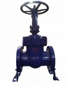
ZJHPF pneumatic fluorine-lined single-seat control valve is a kind of anti-corrosion straight-through single-seat control valve, the inner wall of the valve in contact with the fluid and the components in the valve are made of high-pressure injection molding process, lined with corrosion-resistant, age-resistant polyperfluoroethylene propylene (F46), and PTFE bellows seal. It is widely used in the control of strong corrosive media such as acid and alkali and toxic and volatile gases and liquids.
1. Corrosion resistance. Resistant to almost all media, including concentrated nitric acid and aqua regia.
2. Good sealing performance. Double sealing with bellows and packing to ensure no leakage.
3. The leakage is small. Since the spool and seat are soft-sealed, no leakage is ensured.
4. Equipped with HA actuator, large output force and compact structure. The product conforms to GB/T4213-92.
Type: ZHA(B) multi-spring membrane actuator
Diaphragm material: ethylene propylene rubber clip nylon cloth, nitrile rubber clip nylon cloth Spring range: 20~100, 80~240kPa
Air supply pressure: 140~400kPa Air source interface: Rc1/4°
Ambient temperature: -30~+70°C
Valve action type: the positive or reaction actuator is used to realize the gas-close type or gas-open type of the valve
Accessories: positioners, air filter pressure reducers, position retention valves, travel switches, valve position transmitters, solenoid valves, hand wheel mechanisms, etc
| Effective area cm² | 350 | 350 | 560 | 900 |
| Trip mm | 16 | 25 | 40 | 60 |
| Spring range KPa | 20~100(standard):40~200;80~240;20~60;60~100 | |||
Leakage: less than 0.01% of the valve's rated capacity Return: With positioner: less than 1% of full stroke
Basic error: with positioner: less than ±1% of the full stroke Note: Standard V-type PTFE packing is used
Adjustable range 30:1
| Seat diameter | 3 | 4 | 5 | 6 | 8 | 10 | 12 | 15 | 20 | 26 | 32 | 40 | 50 | 65 | 80 | 100 | 150 | |
| Kv | 0.08 | 0.12 | 0.20 | 0.32 | 0.50 | 0.80 | 1.2 | 2.0 | 3.2 | 5.0 | 8 | 12 | 20 | 32 | 50 | 70 | 00 | 240 |
| Rated stroke | 10 | 16 | ||||||||||||||||
| Seat diameter mm | 20 | 25 | 40 | 50 | 65 | 80 | 100 | 150 | 200 | |||||||
| Nominal diameter mm | 10 | 12 | 15 | 20 | 25 | 32 | 40 | 50 | 65 | 80 | 100 | 125 | 150 | 200 | ||
| Rated flow coefficient kv | straight line | 1.8 | 2.8 | 4.4 | 6.9 | 11 | 176 | 27.5 | 44 | 69 | 110 | 176 | 275 | 440 | 690 | |
| and other percentages | 1.6 | 2.5 | 6.3 | 10 | 16 | 25 | 40 | 63 | 100 | 160 | 250 | 400 | 630 | |||
| Nominal pressure MPa | 0.61.64.06.4 | |||||||||||||||
| Schedule mm | 16 | 25 | 40 | 60 | ||||||||||||
| Flow characteristics | Straight line, equal percentage | |||||||||||||||
| Medium temperature
°C |
-20~200(Room temperature type)、-40~+250、-40~250(Medium temperature type) | |||||||||||||||
| Flange size | The flange sealing surface type is JB77-59, of which the cast steel flange is smooth, and the cast steel flange is concave | |||||||||||||||
| Flange type | Cast iron flange size according to JB79-59, cast steel flange size according to JB79-59 | |||||||||||||||
| Body material | PN (MPa) | 0.6,1.6 | HT200 | |||||||||||||
| 4.0,6.0 | WCB(ZG230-450)、ZG1Cr18Ni9Ti、ZGOCr18Ni12Mo2Ti | |||||||||||||||
| Spool material | 1Cr18Ni9、0Cr18Ni12Mo2Ti | |||||||||||||||
| Upper bonnet type | Normal type (normal temperature type), hot sheet type (medium temperature type) | |||||||||||||||
| Adjustable ratio | 50:1 | |||||||||||||||
Note: We can provide users with ANSI, JPI, JIS flange products, and the flange distance is determined according to user needs.
| Model | ZHA(B)-22 | ZHA(B)-23 | ZHA(B)-34 | ZHA(B)-45 |
| Effective area cm² | 350 | 350 | 560 | 900 |
| Itinerary mm | 16 | 25 | 40 | 60 |
| Spring range KPa | 20~100(standard);40~200;80~240;20~60;60~100 | |||
| Projects | Metric values | Projects | Metric values | ||||
|
Fundamental error % |
Without locator | ±5.0 |
Beginning and end point bias % |
Gas off |
Without locator | Start point | ±5.0 |
| terminal | ±2.5 | ||||||
| With locator | ±1.0 | With locator | Start point | ±1.0 | |||
| terminal | ±1.0 | ||||||
|
Return % |
Without locator |
3.0 |
Air on |
Without locator | Start point | ±2.5 | |
| terminal | ±5.0 | ||||||
| With locator | 1.0 | With locator | Start point | ±1.0 | |||
|
Dead zone % |
Without locator | 3.0 | terminal | 士10 | |||
|
With locator |
0.4 |
1×10⁻⁴×
Valve rated capacity |
|||||


