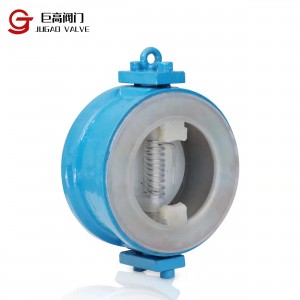
ZJHPF pneumatic fluorine-lined single-seat control valve is a kind of anti-corrosion straight-through single-seat control valve, the inner wall of the valve in contact with the fluid and the components in the valve are made of high-pressure injection molding process, lined with corrosion-resistant, age-resistant polyperfluoroethylene propylene (F46), and PTFE bellows seal. It is widely used in the control of strong corrosive media such as acid and alkali and toxic and volatile gases and liquids.
1. Corrosion resistance. Resistant to almost all media, including concentrated nitric acid and aqua regia.
2. Good sealing performance. Double sealing with bellows and packing to ensure no leakage.
3. The leakage is small. Since the spool and seat are soft-sealed, no leakage is ensured.
4. Equipped with HA actuator, large output force and compact structure. The product conforms to GB/T4213-92.
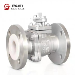
Product type: straight-through single-seat ball valve
DN:3/4',20,25,32,40,50,65,80,100,150mm PN:PN1.6MPa
Flange standard: JB/T79 · 1~79 · 2-94 etc
Material: ZG230-450 lining F46 Operating temperature: -40~180°C
Gland type: bolt pressing type
Packing: V-type PTFE filler
| Nominal diameter(DN) | 20 | 25 | 32 | 40 | 50 | 65 | 80 | 100 | 150 |
| Seat diameter(dn) | 20 | 25 | 32 | 40 | 50 | 65 | 80 | 100 | 150 |
| Rated flow factor (KV) | 5.0 | 8 | 12 | 20 | 32 | 50 | 70 | 100 | 240 |
| Allow the differential(MPa) | 3.8 | 3.2 | 3.0 | 2.0 | 1.8 | 1.5 | 1.4 | 1.0 | 0.6 |
| Nominal pressure(MPa) | 1.6、2.5、4.0、 6.4 | ||||||||
| Rated stroke(mm) | 16 | 25 | 40 | 60 | |||||
| Model of actuator | ZHAB-22 | ZHA/B-23 | ZHAB-34 | ZHA/B45 | |||||
| Spool form | Single seat plunger type fluorine lined valve core | ||||||||
| Flow characteristics | Quick opening characteristic | ||||||||
| Projects | Without locator | With locator | ||
| Fundamental error % | ±5.0 | ±1.0 | ||
| Return % | 3.0 | 1.0 | ||
| Dead zone % | 3.0 | 0.4 | ||
|
Always point off % |
Air on | Start point | ±2.5 | ±1.0 |
| Start point | ±5.0 | ±1.0 | ||
| Gas off | Start point | ±5.0 | ±1.0 | |
| terminal | ±2.5 | ±1.0 | ||
| Rated stroke deviation % | ≤2.5 | |||
| The amount of leakage L/h | 0.01%×Rated valve capacity | |||
| Adjustable range R | 30:1 | |||


| (DN) | 20 | 25 | 32 | 40 | 50 | 65 | 80 | 100 | 125 | 150 | |
|
L |
PN16/25 | 181 | 184 | 200 | 222 | 254 | 276 | 298 | 352 | 410 | 451 |
| PN40 | 194 | 197 | 200 | 235 | 267 | 292 | 317 | 368 | 425 | 473 | |
| PN64 | 206 | 200 | 210 | 251 | 286 | 311 | 337 | 394 | 440 | 508 | |
|
H |
PN16/25 | 52.5 | 57.5 | 75 | 75 | 85.5 | 92.5 | 100 | 110 | 142.5 | 158 |
| PN40 | 52.5 | 57.5 | 75 | 75 | 82.5 | 92.5 | 100 | 117.5 | 150 | 167.5 | |
| PN64 | 65 | 40 | 85 | 85 | 90 | 102.5 | 107.5 | 125 | 172.5 | 195 | |
| H1 | 132 | 132 | 158 | 170 | 179 | 214 | 221 | 234 | 270 | 294 | |
| H2 | 298 | 298 | 298 | 298 | 298 | 380 | 380 | 380 | 510 | 510 | |
| H3 | 180 | 180 | 180 | 180 | 180 | 236 | 236 | 236 | 310 | 310 | |
| L1 | 289 | 289 | 289 | 289 | 289 | 347 | 347 | 347 | 476 | 476 | |
| A | 282 | 282 | 282 | 282 | 282 | 360 | 360 | 360 | 470 | 470 | |
| D | 220 | 220 | 220 | 220 | 220 | 270 | 270 | 270 | 320 | 320 | |