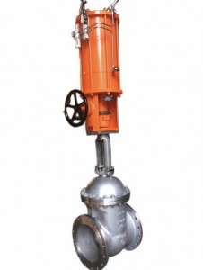
Self-operated electronically controlled temperature control valve (suitable for larger diameter and heat transfer oil control), the biggest feature of the valve only needs ordinary 220V power supply, the use of the energy of the medium to be adjusted, directly to the temperature of steam, hot gas, hot oil and gas and other media to implement automatic adjustment and control, can also be used to prevent overheating or heat exchange occasions, the valve structure is simple, easy to operate, the selection of temperature control range, fast response time, reliable sealing performance, and can be adjusted at will in operation, so it is widely used in chemical, petroleum, food, textile, hot water supply for hotels and restaurants.
Valve body, bonnet: HT200, ZG230-450, ZG1Cr18Ni9Ti
Spool: ZG1Cr18Ni9Ti, Stellcai alloy surfacing reinforced PTFE
Packing: PTFE, flexible graphite push rod, bushing: 2Cr13
Gasket: rubber asbestos board 10, 1Cr18Ni9Ti asbestos wound gasket bellows: 1Cr18Ni9Ti
Before working, the main spool is in the half-open position, and the sensor is in its natural state. Plug in the power supply and the main spool is fully open. The medium flows into the main valve body from the direction of the arrow, and the heat storage box is heated through the valve core. When the temperature rises to the corresponding set value, the sensor will generate the corresponding linear signal input into the integrated intelligent actuator, and then drive the valve stem and valve core to produce displacement, and close the main valve core to stop heating. When the temperature is lower than the set value, the sensor will generate a linear signal input to the actuator, which will drive the valve core to gradually open, so that the medium will flow into the heat storage box according to the parabolic characteristics, and heat up to the set value. In this way, the controlled medium is always controlled within the set temperature range, so as to achieve the purpose of temperature control.
| Nominal pathway DN m m | 20 | 25 | 40 | 50 | 65 | 80 | 100 | 150 | 200 | |||||
| Seat diameter d mm | 10 | 12 | 15 | 20 | 25 | 32 | 40 | 50 | 65 | 80 | 100 | 125 | 50 | 200 |
| Rated flow coefficient KV | 2 | 3 | 4.4 | 6.5 | 10 | 18 | 25 | 40 | 65 | 00 | 150 | 230 | 50 | 540 |
| Itinerary mm | 10 | 16 | 25 | 40 | 60 | |||||||||
| Nominal pressure PN MPa | 1.6,4 .0,6 .4(microtherm:0 .6) | |||||||||||||
| Medium temperature ℃ | Soft seal: -4~+150°C, hard seal: -25~+200°C for normal temperature type, -40~+450°C for medium temperature type, -60~-250°C for low temperature type | |||||||||||||
| Flow characteristics | Quick Open (Flat) | |||||||||||||
| Body material | ZG230-450,ZG1Cr18Ni9Ti,ZG0Cr17Ni12Mo2T | |||||||||||||
| Spool material | ZG2Cr18Ni90Cr17Ni12Mo2Ti | |||||||||||||
| Seat material | Soft sealing: PTFE, reinforced PTFE; Hard seal: 1Cr18Ni90Cr17Ni12Mo2Ti | |||||||||||||
| Flange standard | Cast steel flange:PN1.6 JB82-59,PN4.0,6.4 JB79-59 | |||||||||||||
| Flange type | The flange sealing surface type is: according to JB77-59, PN4.0, 6.4 for the concave seal | |||||||||||||
| Compressed air pressure MPa | 0.5MPa | |||||||||||||
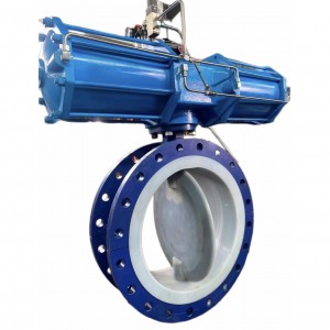
| Equipped with actuators | ZSP series single-acting piston pneumatic actuator | |||||||||||||
| Ambient temperature °C | -25~+60℃ | |||||||||||||
| Allowable leakage Lh | Soft seal: basically zero leakage, hard seal: in line with GB/T4213-92, IV level or above | |||||||||||||
| Standard coating color | Dark blue spray molding | |||||||||||||
| Optional accessories | Air filtration, pressure stabilizer, oil mist triplets, solenoid valves, pipe joints and matching flanges, etc | |||||||||||||
| Nominal diameter DN(mm) | AxB | L | H1 | H2 | |||
| PN1.6 | PN4.0 | PN6.4 | Room temperature type | Hot sheet type | |||
| 25 | 230×460 | 185 | 190 | 200 | 670 | 820 | 104 |
| 32 | 200 | 210 | 210 | 673 | 823 | 107 | |
| 40 | 220 | 230 | 235 | 693 | 843 | 126 | |
| 50 | 250 | 255 | 265 | 698 | 848 | 131 | |
| 65 | 275 | 285 | 295 | 799 | 959 | 175 | |
| 80 | 230×530 | 300 | 310 | 320 | 809 | 969 | 190 |
| 100 | 350 | 355 | 370 | 821 | 981 | 202 | |
| 125 | 410 | 425 | 440 | 872 | 1087 | 250 | |
| 150 | 450 | 460 | 475 | 882 | 1097 | 260 | |
| 200 | 260×630 | 550 | 560 | 570 | 924 | 1139 | 302 |
| 250 | 670 | 660 | 670 | 1156 | 1368 | 422 | |
| 300 | 740 | 785 | 800 | 1215 | 1427 | 484 | |
1. Installation:
(1) Before installation, check whether the product model, tag number and specifications are consistent, and check whether the parts of the whole machine are defective and loose.
(2) Before installation, the pipeline should be cleaned, and there should be enough straight pipe section at the inlet of the valve, and equipped with a filter. The flange connection between the valve body and the pipeline should pay attention to the coaxiality.
(3) Before the shut-off valve is installed, the pipeline should be thoroughly cleaned.
(4) The installation site should take into account the safety of personnel and equipment, which is not only easy to operate, but also conducive to disassembly and maintenance.
(5) The valve should be installed vertically on the horizontal pipeline, and can be installed obliquely as a last resort, so as to avoid horizontal installation as much as possible.
(6) The flow direction of the medium should be consistent with the arrow on the valve body. The air source should be dry and oil-free. The valve should be used in places with ambient temperature -20~55°C.
2. Maintenance:
(1) Cleaning valve: For cleaning general media, as long as it is washed with water. However, for cleaning the medium that is harmful to health, we must first understand its properties, and then choose the corresponding cleaning method.
(2) Disassembly of valves: remove the rust parts on the exposed surface first, but before removing the rust, it is necessary to protect the processing surface of precision parts such as valve seats, valve cores, valve stems and push rods. Special tools should be used when disassembling and assembling the seat.
(3) Valve seat: The sealing surface has small rust spots and wear, which can be carried out by mechanical processing, and must be replaced if the damage is serious. However, regardless of whether the hard sealing surface has been repaired or replaced, it must be ground.
(4) Valve stem: the surface is damaged, and it can only be replaced.
(5) Damage to the pusher, guide and sealing surface: the reaction actuator must be replaced, and the positive action actuator can be used after appropriate repair.
(6) Compression spring: If there are cracks and other defects that affect the strength, they must be replaced.
(7) Wearing parts: packing, sealing gaskets and O-rings, all of which are replaced with new ones during each overhaul. The valve core and diaphragm must be checked for cracks, aging and corrosion traces that may occur in the future, and according to the inspection results, it is decided whether to replace them, but the service life of the diaphragm is generally up to 2-3 years.
(8) The valve assembly should pay attention to the centering, the bolts should be tightened on the diagonal, and the sliding part should be lubricated. After assembly, it should be debugged according to the factory test items and methods of the product, and during this period, the packing pressing force and the valve core closing position can be accurately adjusted.